
User Tools
Table of Contents
USB2AX: Firmware update
The software running in the USB2AX can be updated or changed, to fix bugs, to add new functionalities or to tailor its behavior to your application.
Getting the firmware
The latest official firmware binary can be found on the firmware page.
Also, take the time to check if you actually need to upgrade or if you already have the latest one, the info is on the same page.
Updating the firmware
You have a new firmware and you want to put it in the USB2AX, great! There are three ways to do it:
Regular
For most people, the Regular procedure will work nicely. It is supported by the firmwares made by Xevelabs.
Regular : Windows version
Tested on Win7 64bits.
Get the USB2AX_updater tool (updated Nov 2017).
- Run usb2ax_updater.exe.
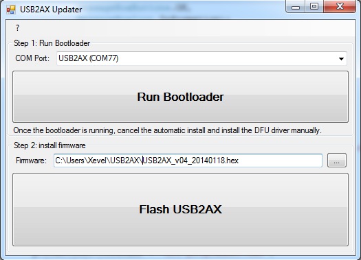
- Select the appropriate COM port and click “Run Bootloader”.
- If it's the first time you do it, the USB2AX will re-enumerate as ATmega32u2 DFU. Cancel the online search for driver, and manually install the driver from the dfu-prog-usb-1.2.2 folder.
- Select the new firmware that you want to upload (without spaces in the path!), and click “Program USB2AX”.
- Done!
Regular : Linux Version
1) Install dfu-programmer >=0.5.4
Maybe add the user to the uucp group so you don't have to run dfu-programmer as root… but it did not work for me.
2) Run the bootloader using the python script: usb2ax_run_bootload.py
Edit it to change the tty port accordingly. It requires Python 2.7 and PySerial.
3) Run the programmer (replace USB2AX.hex by the actual name of the new firmware):
dfu-programmer atmega32u2 erase
dfu-programmer atmega32u2 flash USB2AX.hex
#/!\: with some versions of dfu-programmer, the .hex needed to have UNIX-style end of lines (\n, LF) instead of DOS end of lines (\r\n CRLF)!
dfu-programmer atmega32u2 start
4) Done!
More info for power users
- Running the bootloader on the USB2AX is as simple as sending on its serial port the following ascii bytes: 0xff 0xff 0xfd 0x02 0x08 0xf8 (Python example). Upgrading from version v04 to a newer revision, a second simplified way to do it has been added: open the port at 1200bps, enable DTR, then disable DTR and close the port quickly.
- For commands aimed at the USB2AX, time between two bytes must not exceed 2ms. However, for commands sent to the servos, the maximum byte to byte time acceptable is of 100ms (see http://support.robotis.com/en/product/dynamixel/dxl_communication.htm ).
- When the command is received, the USB2AX removes itself from the USB bus immediately and waits two seconds before re-enumerating.
- The bootloader is the factory-programmed one made by Atmel. On Windows, the USB2AX running the bootloader will appear as ATmega32u2 in the Atmel Devices section of the Device Manager.
Recovery
The Recovery mode is mostly there as a fail-safe: if something goes horribly wrong with the Regular way or if you want to use a third party firmware, you can always get back to a working state without an additional programmer.
Doing that is a two step process: running the bootloader, then uploading the firmware into the flash memory. Only the first part is detailed here since the second is the same as in the Regular way.
Please be aware that attempting these is done at your own risks!
Running the bootloader manually
To run the bootloader manually, you need to get access to the pads on the bottom of the board. Either remove completely the clear protective plastic or just cut out the part that exposes the 3 pads on the side of the board.
The 3 pads are labeled GND, HWB and RST. The goal is to be able to connect GND with the two others, then release RST, then release HWB more than half a second later. There are various ways to do it, here are some suggestions.
- with two buttons (requires soldering)
Solder a button between GND and HWB, and the other one between GND and RST. Press the two buttons, then release the one that goes to RST, and a second later the other one.
- with a button and a capacitor (requires soldering)
Solder a small capacitor (in the uF range) between GND and HWB, and a button between GND and RST. When you press the button for a second or two, this will discharge the capacitor, and when you release the button, it should keep the voltage on HWB low enough for long enough for the bootloader to run.
- with tweezers or a piece of wire
Take a pair of metallic fine tweezers or a piece of wire with stripped ends, touch one end on the GND pad and the other one successively on HWB (leave it for a second) and RST (just touch it). You will get better results if you switch from one to the other very quickly. If you are lucky, the stray capacitance of the HWB trace maintains it low enough for long enough for the bootloader to run.
ICSP
The ICSP method allows you to change the bootloader or do away with it to use the full 32k of FLASH, but requires an ICSP programmer and some soldering.
To connect the ICSP to the board, the necessary pads are broken out on the bottom side. You will need to remove the clear protection around the board, then connect:
ICSP pin number ↔ pin functionality ↔ place to get it on the USB2AX
- ↔ MISO ↔ PB3 pad
- ↔ Target VCC ↔ USB pin under the point of the version number “v3.1a”
- ↔ SCLK ↔ PB1 pad
- ↔ MOSI ↔ PB2 pad
- ↔ RST ↔ RST pad
- ↔ GND ↔ one of the GND pads
The rest is up to you, from there it's like programming any other AVR MCU. Have fun!
Customizing the firmware
The sources of the firmware are available in the Git Repository of the project.
Read the README file to get an idea of what is going on, read the code, and start hacking away!
